 |
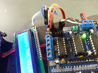
| LCD mounted on Woody Bot |
The Sainsmart IIC/I2C/TWI 1602 Serial LCD Module Display module allows you to display information directly on your project and also gives you the ability to interact with the Arduino directly by adding a few switches here and there. Having this ability is a great way to troubleshoot your project and have it interact with others.
SainSmart IIC/I2C/TWI 1602 Serial LCD Module Display For Arduino UNO MEGA R3 *New *

Choose a Display
When you decide to add an LCD readout to your Arduino project you will have to decide on a few things. What size, color and interface type do you want. Size is relevant to how much data you want to display at once. Color is personal preference mostly. Interface is largely a choice the number of free inputs/outputs left on your project and your technical abilities. I started by trying to add an old 16x2 display I had from an old plotter. This is doable, and in fact done all the time. My problem was it took 7 pins to run the lcd and I don't have that kind of real estate with an Arduino UNO R3 and a Motorshield on top. So I opted for an LCD model that incorporates the I2C interface board.

What is I2c

Lcd2004 with I2C Module on back.
I2C, read I Squared C is a two wire interface for slower speed devices that allows the Arduino to become a master controller of the slave device and send it commands that only require two wire connections to operate the device. So we go from 7 wires to only 2 to have a functioning LCD read out. The kewl part is that if you had more than one device that was I2c, you could use them on the same two pins. That is a pretty nice feature to have. The I2C Module on the back also incorporates a built in contrast pot. One less thing you have to design, wire and build.
Data and Clock Pins
The SCA(data) and SCL(clock) wires are the I2c connections needed to use this readout. On the Arduino Uno they are the A4 and A5 analog pins. On the MEGA board they use the Pins 20 and 21. I wasn't able to find a way to change this on the UNO boards, but it may be possible. I had to move a Ping sensor I installed earlier on pin A5 because of this.

100 Ohm resistor on 5 volt
Power
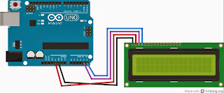
The LCD2004 is s 5V device, so we have to clarify that even though the I2C only uses two wires for data, this is still a 4 wire LCD in that it uses 2 wires to supply data and 2 more wires to supply power and a ground for the device to run. I ran the data wires to the Breadboard I made on the motorshield on pins A4 (SCA) and A5(SCL). I then ran the power wires to the two pins behind port A5. Make sure you put a 100 Ohm resistor on the 5v+ side or your lcd will not work correctly. In the diagram They didn't have an IC2 LCD so I ran the wires to a regular LCD. Red is 5V(vcc) Black is Grd. Purple is SCA(Pin A4)and Blue is SCL(Pin A5).
Code
 The code for your new LCD is pretty simple once you find the right library. I struggled to find one that worked. The first thing I did was goto Sainsmart's site and download their library. One thing we know about Sainsmart is that the website is not up to date and half the stuff you have to hack away at to make it work. But that is the price you pay for cheap prices. Their library did not work for me. After a lot of research I stumbled across a guy who said that this unit was the same as one released by a company called DFRobot. So I tracked it down and found a library there that seemed to work very well. Go to DFRobot LCD and scroll to the bottom to download the library. The name is LiquidCrystal_I2Cv1-1.rar. Download and install it in your Arduino programmer. There are newer libraries but this one is the one works great with this LCD.
Add Code to Sketch
Next we need to add code to our sketch to make it work. Add the following two line in the section above your void setup().
#include <LiquidCrystal_I2C.h> //Include the installed library
LiquidCrystal_I2C lcd(0x3f, 16, 2); // set the LCD address to 0x3f for a 16 chars and 2 line display.
The default codes all have this (0x3f) address wrong, make sure you know the address of your lcd. Making sure its connected and ready with the I2C Scanner tool found here. Put the address it finds in the line above.
In void setup() add the following lines.
voidSetup()
{
lcd.init(); // tell the lcd to be ready for data.
lcd.backlight(); // Turn on the back light, you can also do this in a function.
}
Add the following lines to your void loop() section.
void loop()
{
lcd.print("Hello There!"); //print on line 1 of the LCD
lcd.setCursor(0,1); //set the cursor to line 2
lcd.print("Im an Arduino"); Print on line 2
delay(100);
}
Here is the complete Woody bot Code with the LCD Added. I rewrote the code I used previously to utilize functions instead of all the code in a linear line. It makes it much easier to edit and troubleshoot the sketch later. This sketch includes status updates when the bot avoids an obstacle.
//Code for the Woody Bot, with Ping Sensor, and LCD2004 readout // //Kevin "Woody" Woodyard // //Check out http://woodystime.blogspot.com for more info and build guide. #include <Ping.h> #include <AFMotor.h> #include <Wire.h> #include <LiquidCrystal_I2C.h> LiquidCrystal_I2C lcd(0x3f,16,2); // set the LCD address to 0x27 for a 16 chars and 2 line display Ping ping = Ping(A3); //set which model ping your using AF_DCMotor motor(1, MOTOR12_64KHZ); //Set motors to right frequency to match your servo. // create motor #1, 64KHz pwm AF_DCMotor motor2(2, MOTOR12_64KHZ); // create motor #2, 64KHz pwm void setup() { Serial.begin(9600); // start serial communication at 9600 baud lcd.init(); // initialize the lcd lcd.backlight(); lcd.print(" Woody Bot");// Print a message to the LCD. lcd.setCursor(0,1); lcd.print(" Version 1.4"); //Print on line 2 of the lcd delay(3000); pinMode(A0, INPUT_PULLUP); // make pin A0 an input with internal pullup motor.setSpeed(255); // set the speed 0f the servos motor2.setSpeed(130); while (digitalRead(A0) == HIGH){ // Pause until the button is pressed lcd.setCursor(0,1); lcd.print(" Press Start! "); } } void loop() { Scan(); int inches = ping.inches(); // where are we??? Forward(); if(inches <= 6) { // if the Woody Bot gets too close... Left(); }else{ Forward(); } } void Scan(){ for(int i = 0; i<5; i++) // do this 5 times ping.fire(); } void Forward(){ //Run both motors forward lcd.setCursor(0,1); lcd.print(" ^^^Forward^^^ "); motor.run(FORWARD); motor2.run(FORWARD); delay(100); } void Left(){ //Run Motors opposite to rotate left. lcd.setCursor(0,1); lcd.print(" Turn Left "); motor.run(BACKWARD); motor2.run(FORWARD); delay(300); } void Right(){ //Run Motors opposite to rotate right. lcd.setCursor(0,1); lcd.print(" Turn Right "); motor.run(FORWARD); motor2.run(BACKWARD); delay(300); }
Comments